
 |
Home | Articles | Projects | Products | Bookmarks | About |
Posted at - 27th September 2017
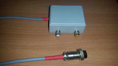
I made this interface because I wanted to transform my bitx transceiver into a beacon primarily to test propagation conditions sometimes and to enjoy the other beautiful side of ham radio, working on digital QSOs.
Again, I didn't considered very important to draw this simple schematic in *CAD.
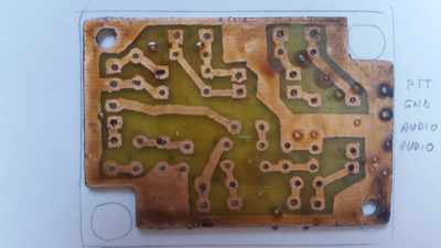
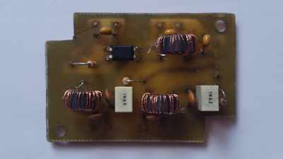
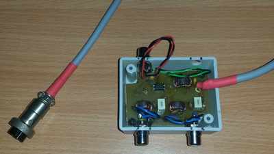
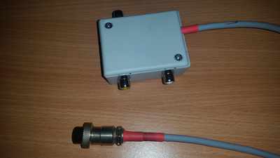
The interface mainly does nothing more than connecting audio outputs to audio inputs and switch between Rx/Tx. Therefore, audio output from transceiver is connected to microphone input from PC, and audio input (microphone) from transceiver is connected to audio output from PC. For receiving/transmitting command a pin from RS232 serial port is used.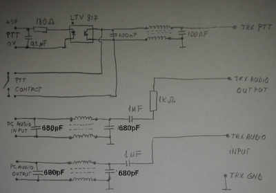
The audio lines are on the middle and the bottom of schematic. It can be seen that the audio output from transceiver is connected to the audio input of PC and audio input from transceiver is connected to audio output of PC. The 680pF capacitors and common mode chokes filters out the residual RF if any. The 1uF capacitors separates DC between PC and transceiver.
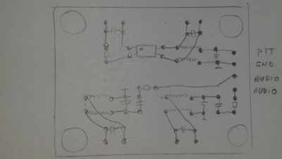
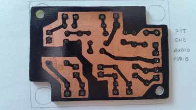
Depending of computer audio mixers settings or transceiver design, microphonics oscillation can occur. In my case, I think the bitx design creates this phenomenon because of common path in audio lines. The microphonics can be suppressed adjusting the audio volume from bitx below oscillation threshold, unfortunately the volume in computer speakers will be lower then.
I successfully used this interface in conjunction with bitx and fldigi on digital QSOs (RTTY, BPSK-31/BPSK-63). With 2xIRF510 50W amplifier and 20m long wire antenna from Bucharest Romania, I worked Spain, Germany, Finland and Russia on 3.5MHz, max. distance being ~2800Km.
 |
Home | Articles | Projects | Products | Bookmarks | About |