
 |
Home | Articles | Projects | Products | Bookmarks | About |
Posted at - 25th April 2017
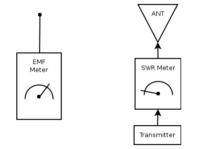
EMF Meter or Field Strength Meter is a device that measures surrounding electromagnetic field. That means you will be able to see the real radiation from your antenna without interconnect it in the antenna's feed line as you'll do in case of SWR meters. Therefore, it is useful to adjust antennas, transmitters, or tunners between them by analyzing the electromagnetic field. For a good setup you may use both EMF meter and SWR meter correlated together like in picture below.
Electromagnetic waves excite electrons in antenna forcing them back and forth, producing little alternative currents. Using different methods of rectification, amplification, these little currents can be transformed into readable values.
For example, if a light bulb is attached to the ends of a dipole antenna in a presence of electromagnetic radiation electrons start to flow from an element to another through filament, so if the field is strong enough the light bulb will glow (Fig. 2A). This case does not apply for LED, because it is a diode and will restrict electrons to flow in one direction only. The LED doesn't glow because once the electrons of one element are pushed into another through LED there's no path for them to return back (Fig. 2B) thus leading the dipole elements positively and negatively charged. The LEDs are poor switching diodes (high forward voltage, big capacitance, high leakage current, poor rectification efficiency, etc), however if you connect two LEDs in antiparallel mode (Fig. 2C) at the ends of the dipole and if the electromagnetic field will be of low frequency, they will glow, one each for one half cycle, but you will see them both glowing the same light at the same time due the high speed of frequency. You won't notice any flickering even for low frequencies as 200Hz.

On the internet I've found a lot of bad schematics. Many of them does not measure in a linear way or they are not sensitive enough, other use some ICs, etc. An interesting IC is AD8307 which is a fully integrated 0-500MHz logarithmic amplifier, very precise and easy to use. But I don't want to use ICs, so I decided to write down the main objectives:
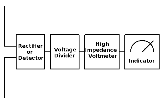
Now we've got a basic ideea about how a receiving antenna works, it's time to design our EMF meter. First of all, the alternatig current at the ends of antenna must be sampled somehow, then rectified-detected, amplified and finally displayed to the user. After some experiments on the breadboard I drew the following conclusions:
1. A high impedance voltmeter should be used in order to prevent loading of the detector/rectifier stage. The voltmeter should be immune to changes in temperature and power supply voltage.
2. Also, a resistive divider should be used in order to set the ranges of the voltmeter. The resistive divider will set the input impedance of the voltmeter.
3. A frontend transistor which follows the antenna cannot be used because it will truncate the broadband characteristics of the diode. It must be used in a tuned configuration. If a transistor is used though, its dynamics cannot handle cases when high voltages develop across the antenna ends. A such case occurs when you place receiving antenna next to the transmitter's antenna which is powered by more than 5W HF/VHF, voltages high above 20Vp can develop at the receiving antenna.
The block diagram looks like this:
With many years ago I've bought a cheap analog micro ampermeter for this purpose. An analog meter will indicate realtime fluctuations, unlike digital one which will measure voltage in samples per second. A full scale deflection on it indicate 50 uA with approx. 2.2 Kohm coil resistance. With a such low resistance it cannot be connected directly to the divider, thus on detector stage beacuse of loading issues, basically it will disturb detector's output. Therefore, there needs to be a high impedance adapter between them. I tried to use some BJTs without success though, so a JFET it's a must for this job.
JFET has a very high input impedance, tens or hundreds of megaohms for DC. I have found a bounch of BF256B in my junk box, so I'm going to use this type of JFET for my EMF project. For a good understanding of this type of transistor, please read the JFET article in SEMI section on http://allaboutcircuits.com
This testing circuit can be used to find its linear region.
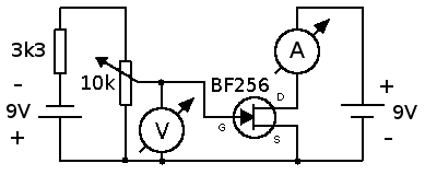
The following table represents measurements taken from voltmeter and ammeter while gradually turn the potentiometer.
| Gate-Source Voltage | Drain Current |
|---|---|
| -3.00V | 0.00mA |
| -2.75V | 0.09mA |
| -2.50V | 0.40mA |
| -2.25V | 0.86mA |
| -2.00V | 1.50mA |
| -1.75V | 2.24mA |
| -1.50V | 3.00mA |
| -1.25V | 3.90mA |
| -1.00V | 4.90mA |
| -0.9V | 5.32mA |
| -0.8V | 5.74mA |
| -0.7V | 6.19mA |
| -0.6V | 6.60mA |
| -0.5V | 7.00mA |
| -0.4V | 7.50mA |
| -0.3V | 7.99mA |
| -0.2V | 8.47mA |
| -0.1V | 8.94mA |
| -0.0V | 9.40mA |
In the first part of this table the bias voltage was incremented by +0.25V units, while in the second part of the table the bias voltage was incremented by +0.1V because a better resolution is wanted from the linear region.
Plotting this as a graph:
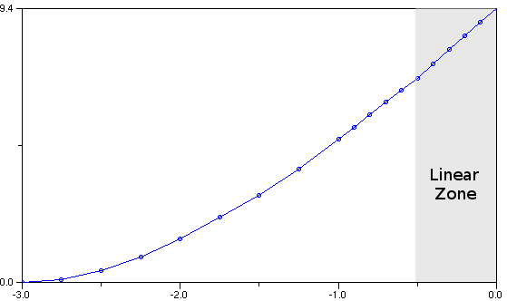
After a short analyze of both table and graph, it can be seen that in linear region, a change of +0.1V above -0.5V at the Gate will increase the Drain current about 0.50mA.
In order to use this linear portion as voltmeter, the JFET must be biased in a such way that the Gate-Source voltage must be set at -0.5V as starting point and for each increasing unit of 0.1V to read +10uA deflection on the indicator scale.
A full scale deflection on this meter will indicate 50uA. Its scale representing 0uA, 10uA, 20uA, 30uA, 40uA, 50uA.
The following table should reflect correlation between Gate bias voltage and uA readings:
| -0.5V | 0uA |
| -0.4V | 10uA |
| -0.3V | 20uA |
| -0.2V | 30uA |
| -0.1V | 40uA |
| 0V | 50uA |
To obtain -0.5V Gate-Source, the transistor must be connected like schematic below, where Rs can be calculated from these: Voltage across resistor must be 0.5V and current through 7.00mA (see 2nd table above). Then Rs = U/I, that means Rs = 0.5/0.007 => Rs = 71.4 Ohms.
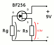
Since through Rg does not flow any current, due JFET very high impedance, the voltage across it is 0V. No matter what value Rg has, it will be like a shunt shorting the gate to ground. If a voltmeter is connected with red lead to Gate, and black lead to Source, reading will be -0.5V, the Gate is reverse biased! A big care should be taken while measuring the Gate-Source voltage, if Rg is about 10MOhms, and the impedance of measuring tool is less about 100MOhms DC, it will show an erroneous measurement.
In order to measure those 0.50mA units from drain current, the analog meter should be placed between two voltage dividers like in a wheatstone bridge.
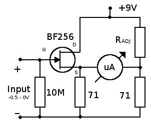
When the two legs of the bridge are balanced, i.e. same current flows through both legs, there is no current flow through uAmmeter, therefore no readings. Radj should imitate characteristics exhibited by JFET thus will balance the bridge. Across 71 Ohm resistors will be 0.5V drop, while on the BF256 and Radj should be 8.5V drop, both legs has 7mA through, so the total current when no readings will be 2 x 7mA = 14mA, Radj = 8.5 / 0.007 => Radj = 1214 Ohms.
If the Gate voltage raises from -0.5 to 0V, current through 71 ohms resistor will be about 9.4mA, which means 0.64V. On the other leg of bridge, across 71 ohm resistor will be about 0.5V, so between the two legs will be a difference about 0.14V. The uAmmeter has an internal resistance about 2.2K, then 0.14 / 2200 = 63uA. The uAmmeter will read about 63uA but its scale can read a maximum of 50uA, therefore a resistor must be placed in series with uAmmeter in order to read 50uA full scale deflection for 500mV voltmeter input. Its value can be found easely, 50uA on 2.2K means 0.11V, so 0.14 - 0.11 = 0.03V must be dropped across series resistor, its value equals about 600 ohms.
This type of wheatstone configuration is super sensible to variatons in power supply voltage, which means bad news when it is powered from battery. Also, temperature fluctuations of the resistors or transistor will lead to erronous measurements, because in general if the temperature is increasing, the resistors will raise their values while the transistor will lower its resistance, resulting in a very unbalanced legs of wheatstone configuration.
To get rid of this, a null calibrator must be added, a potentiometer replacing Radj which will set zero reading for 0V voltmeter input, every time when it is turned on. Or a better method is to use same components for both legs of this wheatstone configuration and no null calibrator is needed then. For this task, components must be carefully sorted. Resistors must have same value, transistors same linear curve, same transconductance.
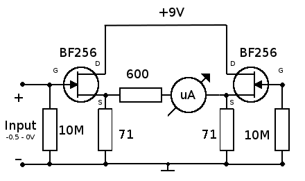
Unfortunately, at build time I didn't find any apropriate resistor to 71 ohm, so I used 68 ohm with similar results, but the 600 ohm resistor was replaced by a trimmer, the bias voltage slightly changed too.
According to uAmmeter scale, voltmeter should measure milivolts as following:
| 100mV | 10uA |
| 200mV | 20uA |
| 300mV | 30uA |
| 400mV | 40uA |
| 500mV | 50uA |
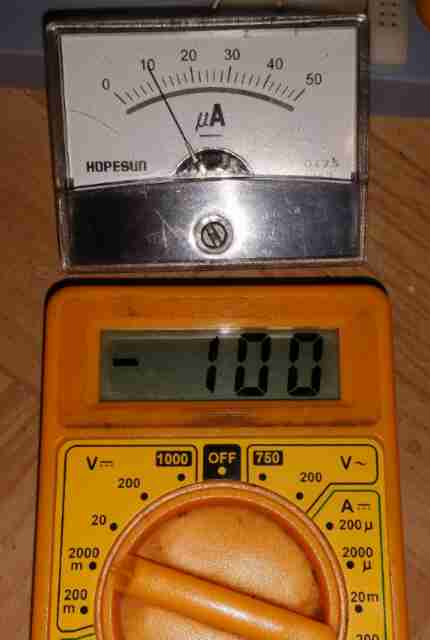
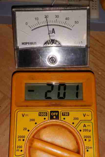
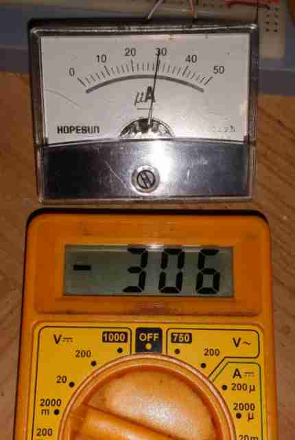
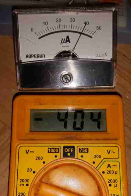
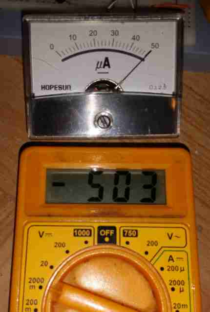
Construction photos:
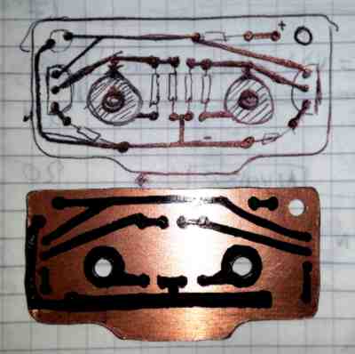

The JFET voltmeter now can measure voltages from 0 to 500mV. I think that a range from 0V to 50V should be sufficient for my EMF meter, also that 50V limit will be imposed by the maximum detector brakedown voltage (described in the next section). In order measure between this range a voltage divider with three steps is needed.
The ranges will be:
0V to 0.5V
0V to 5V
0V to 50V
The voltage divider will have a total impedance of 10Mohms for DC and will replace the 10Mohm gate resistor from voltmeter's input. Voltage across divider resistors can be calculated using this formula:
Us = U * (Rs / Re)
Us - voltage dropped across selected resistor;
U - voltage across entire divider resistance;
Rs - value of selected resistor;
Re - equivalent resistor value of entire divider.
This can be explained as voltage multiplied by resistors ratio, while resistors ratio means how smaller is one resistor than the total equivalent one, same times smaller will be the current, the voltage, across smaller resistor. So, if our input is 4.5V we should reduce this voltage to 450mV, ten times smaller. Using formula results Ur = 4.5 * (1000000 / 10000000) => Ur = 0.450V, which is correct. Same for 36V input, on the gate of JFET we'll have Ur = 36 * (100000 / 10000000) => Ur = 0.36V.
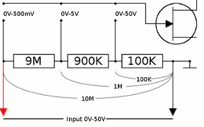
All resistors must be 1% precision for the divider.
Sampling voltages from antenna can be done with several methods:
The diode clamper circuit used in my EMF:
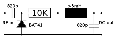
When a RF voltage is present at the input, for one alternance, the 820p capacitor will be shorted to ground by the diode and charged to RF peak value with positive side to 10K resistor. Once charged, its stored voltage will be added together with RF voltage average value which is 0V, so if the peak value is 10V, voltage measured by the detector will be 0V + 10V = 10V. Of course, the diode will have a voltage forward drop, BAT41 has about 350mV, then the real voltage exhibited by the detector will be 0V + 10V - 0.35V = 9.65V. Maximum RF voltage supported by the detector is set by the diode reverse voltage. When the capacitor is charged and one alternance will add toghether with capacitor stored voltage, there will be 50Vp RF + 49.65V capacitor = 99.65V reverse voltage across the diode, since the BAT41 diode has a maximum of reverse 100V, then the breakdown voltage of the detector is half of the diode reverse voltage. The following resistor, coil and the output capacitor forms a low pass filter, removing any residual RF. The 10K resistor also protects the voltmeter from high currents. Capacitors should rated above the diode reverse voltage also.
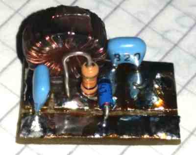
Firstly, when I have tested this clamper circuit, I didn't used the 820p capacitor at the input (it was no longer a clamper circuit) and I have observed on the scope that the diode shunts the signal for one alternance thus it can't be used as a RF probe, therefore the input capacitor is really needed! The detector can be used as a RF probe without a visible impact to the measured circuit due its high impedance.
I tried to get a better alternative for that BAT41 diode, but after some datasheets analyzation I came across to the following conclusion: super high frequency diodes have a small jonction in order to exhibit less capacitance, thus they are available only with low reverse voltages i.e. 2-12V. Almost all diodes have a non linear region ranging from 0mV to approx. 1000mV, measuring small signals in a very non-linear way. Even though, for a range of 0-200Mhz and medium reverse voltage, the BAT41 does its job for me.
To build the EMF meter I used a small alu case, 9V alkaline battery, a BNC jack, rotative switch, knob, and other smaller stuff. Everything was carefully measured and maybe more than an hour of thinking about how to place them in that small box. The hard work was drilling and milling the thick alu case.
Front view:
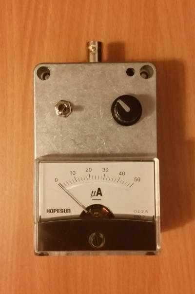
Back view:

1 - voltmeter
2 - divider + rotative switch
3 - detector
4 - 9V battery
5 - ON/OFF switch
6 - BNC jack
Unfortunately, I didn't found high precision resistors for the divider in my junk box. But all components were carefully selected to provide best match.
The whole circuit draws about 13.5mA in idle state and 15.2mA at full deflection on the scale, with those 68 Ohms resistors on JFET source. An alkaline 9V battery which is rated to 550mAh typically will power the EMF meter about 25-30 hours continuously. Because there is no battery indicator and the rotary switch has unused pins remaining, would be nice to have a clue about battery charge. Another voltage divider will divide the supply voltage in order to be measured by voltmeter when knob position is selected accordingly.
Voltage divider for battery measurement will be composed from two resistors, 9.5M and 500K which will set full deflection on the scale at 10V. Of course at build time I didn't found any suitable precision resistors, therefore ordinary resistors were used with values 9.1M and 470K.
Calculated battery measurements:
| 9.1M + 470K | 9.5M + 500K | ||||||||||||||||||||||||
|---|---|---|---|---|---|---|---|---|---|---|---|---|---|---|---|---|---|---|---|---|---|---|---|---|---|
|
|
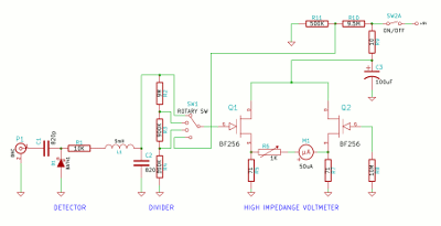
The final schematic: (click to enlarge)
Using a piece of 30cm of wire as an antenna the EMF meter is sensitive enough to get weak needle movements at 6-7 meters away from a 5W VHF handheld, plus two concrete walls in between. The UHF sensitivity is worse due the diode poor characteristics. On 80m HF it can pick up signals several meters away from a dipole antenna powered by 4W CW. Even more, if I plug the external HF antenna to the EMF meter I get readings about 600-800mV because of a powerfull (250KW) medium wave (855KHz) transmitter located about 30KM away.
Another VHF test was to set a dinstance between my handheld and EMF-meter to read a steady 1V on the scale at 50mW output, then when I switched the power level to 500mW the readings raised to nearly 3V, which confirms about 10dB increasing.
Using the EMF-meter in parallel with the scope, it measures approx. same peak voltage as scope does. The measurements are not quite accurate due low precision resistors used in divider network. For example, EMF-meter measures 5Vp the scope 5Vp, EMF-meter 11Vp the scope 10Vp, EMF-meter 17Vp the scope 15Vp and so on.
I'm planning to change resistors used in dividers network with precision ones, but meanwhile the EMF-meter can be used as a reference tool to see fluctuation in EM field and as RF probe.
In order to transform voltage readings to dB the following formula can be used: 20 * log (Vmax / Vmin). So, a reading from 10 to 50 on the scale is equivalent to an increase of 13.9dB.