
 |
Home | Articles | Projects | Products | Bookmarks | About |
Posted at - 28th May 2017

Because I wanted to replace my old, bulky, heavy, crappy power supply, I have designed a new one aiming the following:
I plan to use it as a general power supply, charging accumulators, providing current for my QRP transceivers, etc. From my experience, I found cheap switching power supplies very noisy regarding RF emissions especially for HF spectrum, therefore for this power supply I'll use a 50Hz power transformer. A toroidal transformer was chosen over a classical E-I one, because of its high efficiency and weight/power ratio.
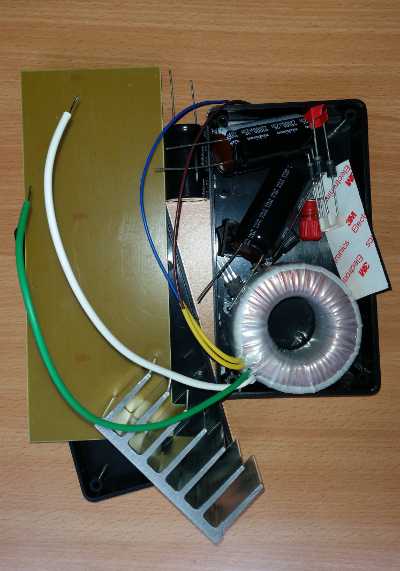
After an hour of looking on TME about components and their characteristics, finally I found the right transformer 18V 1.7A 32VA 480g.

The LM317 claims to have overload thermal protection, current limiting protection, very good ripple rejection, 1.5A, adjustable voltage. So, it was very well suited for my project. The D5 and D6 provide low impedance discharge path for C4, C5, C6 and C3, protecting the LM317 circuit. The C3 is used to further reduce the ripple rejection. RV1 and R1 are required to set the output voltage. According to LM317 datasheet, the output voltage can be calculated using the following formula:
Vo = Vref * (1 + RV1/R1) + (Iadj * R1)
where,
The filter is used to cancel out the noise coming from main line acting as a common current choke. It is formed from two twisted conductors of 1mm diameter wound on a KEMET ESD-R-25D-8 toroidal core.
The last electrolytic cap of 22000uF/25V is used to further smooth the current. I have intended to use a 22000uF for C2 too, but I didn't had one with big voltage rating at that time, so 10000uF/35V was used.
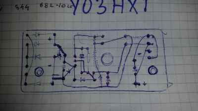
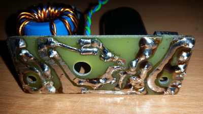
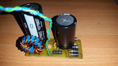
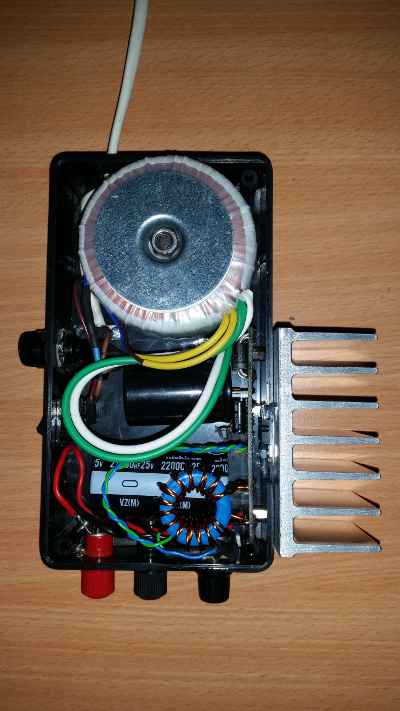
When used to power my 80m QRP 5W transceiver it does not introduce any hum or noise, nor for transmission, neither for reception, which is exactly what I wanted.
It weighs approx. 1.04Kg.
 |
Home | Articles | Projects | Products | Bookmarks | About |