 |
Home | Articles | Projects | Products | Bookmarks | About |
Posted at - 3rd November 2017

I always wanted to have a good reception of LF/MF/HF bands on my Kenwood TH-F7e, therefore I tried diferent kind of antennas.
After the above experiments I understood that Kenwood TH-F7 is too sensible for another amplification stage or for full size antennas. The antenna system should have the following characteristics: passive, low noise for indoor use and tunable for each portion of the band. The answer was: Passive Magnetic Loop Antenna.

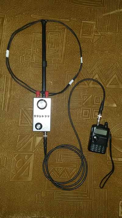
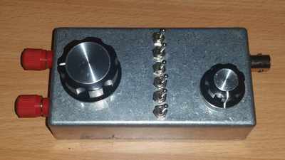
The case was especially chosen to be a solid aluminium box which can fit into the palm and carefully designed to be easily operated with only one hand, the holding hand. So, the big knob and the switches in the middle are used to tune to the frequency and the small knob is used to change the impedance matching. Two banana plugs were used to connect different loop antennas, making room for further experiments. A BNC connector at the bottom will connect the unit to the transceiver.

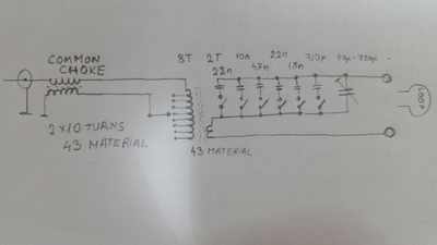
As it can be seen, the schematic is super simple. It consists mainly from some tuning capacitors and an impedance transformer. When the loop is connected to the circuit it will form a sort of tuning tank together with capacitors. The electrons in loop/coil wire will be moved by an alternating magnetic field which resonates on the same frequency, more or less. That tuned tank which resonates on some frequency will have some impedance too, usually very low impedances for low frequencies. The transformer will convert those high/low impedances to 50 Ohms of transceiver, in this case Kenwood TH-F7. After all these, a common current choke will wipe out interferences of high frequencies coming from the electric field between the loop and the transceiver grounding system / transceiver case.
The tuning capacitor can tune from 40pF to 40nF continuously, thanks to the Polycaricon variable capacitor (40-720pF) and to 6 bit like switches which they always doubles up the capacity. All ceramic capacitors are rated at several kV. First switch from right will add 720pF to the variable capacitor, then the second switch will add 1.5nF, third adds 2.2nF, fourth 4.7nF, 10nF, 22nF. With all switches to ON position and with variable capacitor to max value a total of 40nF can be reached.
The resonance happens when impedance will be pure resistive for a given frequency, inductance and capacitance cancels out each other. Let's say we have 12uH coil and 40pF tuning capacitor. To find the resonance point: F = 1 / (2 * Pi * √(LC)) => 7.2MHz and the impedance Z = √(R2 + (Xl - Xc)2) => 550 Ohms. The capacitors can be tuned up to 40nF, so for 12uH the resonane will be 230KHz with impedance of 15 Ohms
So far, so good! But to read signals picked up by the tuned tank it should be somehow connected to transceiver. Therefore, the transformer does two things, reads current through tuned circuit and change its impedance. Of course, it will add some load to the tuned circuit, so the resonance frequency will be a bit lower than expected.
The transformer should be able to transform impedances between 10-500 Ohms to 50 Ohms, that means impedance ratios between 1:5 - 10:1, translated to turn ratio 1:2 - 3:1. Impedance depends on the inductance of the loop and tuning capacitors, so very often the loop will be small and have less inductance for a given frequency while the capacitors will have a big capacitance, thus resulting into low impedances most of the time. The transformer will be made mainly as a step up transformer, but it should be able to step down too.
Making 2 turns as primary and 8 turns as secondary, resulting in a turn ratio of 1:4 with impedance ratio 1:16. And because the primary has two turns one turn can be tapped into secondary, meaning a turn ratio of 2:1, impedance ratio 4:1. Likewise, it could work as a step up or as a step down.
Now coming the loading part... In order to add a less inductance to the tuned tank and less load I used a small toroidal core because of its low inductance per turn and small mutual coupling, the signal transfer will be a bit lower too. The core is a FairRite 43 material (5943000201) which has an AL value of 350nH, therefore two turns gives about 1.4uH (L = AL * Turns2) which they add to the tuned tank lowering the resonance frequency. Using this 1:16 - 4:1 impedance transformer, our 50 Ohms load from transceiver is magnified or lessen from 3 Ohms to 200 Ohms which also adds in series with the capacitors and coil in tuning tank limiting the current flow.
As I said, unwanted electric field could be picked up messing up our loop characteristics. The unwanted electric field can move electrons between loop and transceiver case through transformer's parasitic capacitance, the whole system acting like an open dipole, even if the loop is balanced. To prevent somehow such behaviour, a common current choke is used.
It is made of 10 turns of twin wire on the same toroidal core as the impedance transformer. It is supposed to filter out HF and VHF electric field interferences.

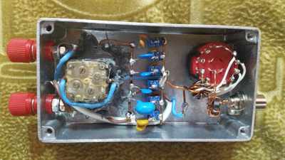
The variable capacitor was recovered from an old radio set. It doesn't have any fixing system, therefore it was glued with a strong epoxi cement.
I tested this antenna even for QRP transmitting and it seemed to work but the transformer's core gets hot with 5W on 80m.
 |
Home | Articles | Projects | Products | Bookmarks | About |